Cmos Circuit Diagram For Full Subtractor
Subtractor circuit – half subtractor, full subtractor, how it works Multiplexer circuit logic gate mux using subtractor implementation digital inverter symbol bit line multiplexers selector surrey ac electronics above source Implementation of low power 1-bit hybrid full adder using 22nm cmos
multiplexer - Design a full subtractor using 4 to 1 MUX and an inverter
Cmos schematics nand Subtractor circuit half circuits Half subtractor adder sub tutorial electronics logic borrow output circuits
Cmos circuit schematic diagram
Vhdl tutorial – 11: designing half and full-subtractor circuitsAdder cmos implementation Subtractor half circuits truth table vhdl designing tutorial circuit sub.
.

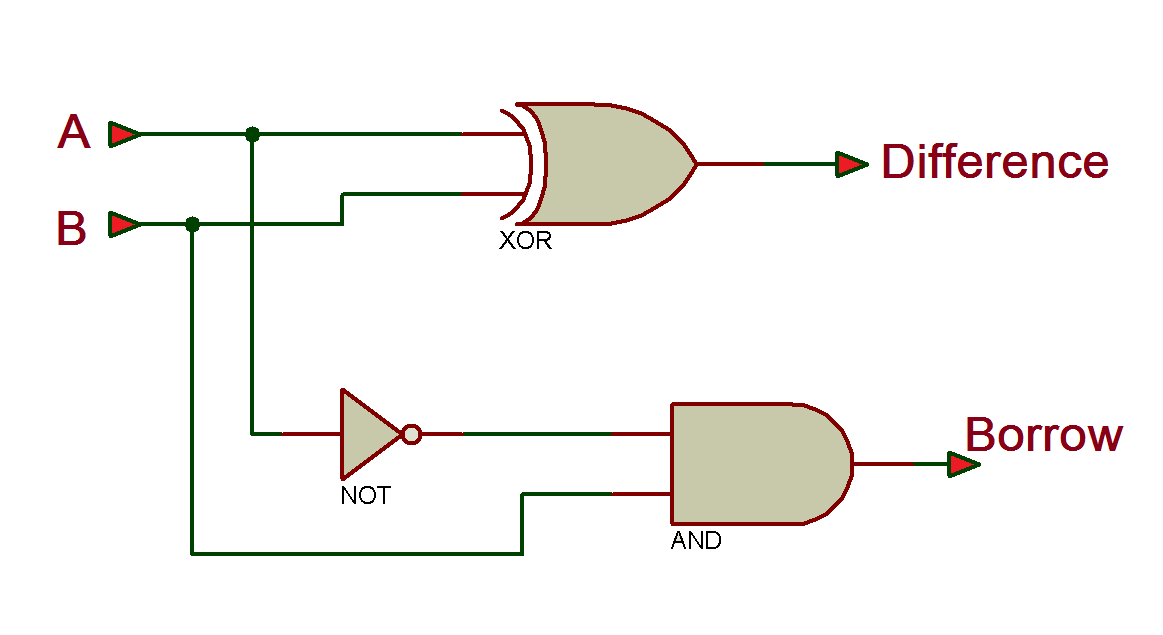
VHDL Tutorial – 11: Designing half and full-subtractor circuits

Half-Subtractor | Electronics Tutorial

Cmos Circuit Schematic Diagram - Wiring View and Schematics Diagram

Implementation of Low Power 1-bit Hybrid Full Adder using 22nm CMOS

multiplexer - Design a full subtractor using 4 to 1 MUX and an inverter
